DFI CM33-TC User Manual

Browse online or download User Manual for Motherboards DFI CM33-TC. CM33-TC

  • Download
  • Add to my manuals
  • Print
  • Page
    / 1
  • Table of contents
  • BOOKMARKS
  • Rated. / 5. Based on customer reviews
Page view 0
CM33-TC
Power Select for USB 1, 2
(JP1) or USB 3, 4 (JP10)
1-2 On: VCC (default)
2-3 On: 5VSB
Onboard Audio Codec
Settings - JP4, JP5 and JP6
1-2 On: Enable (default)
2-3 On: Disable
Clear CMOS Data - JP3
1-2 On: Normal (default)
2-3 On: Clear CMOS Data
3.3VSB Standby for PCI -
JP2
On: Provides 3.3VSB standby
power to the PCI slots.
(default)
Off: For PCI modem cards
that does not comply to PCI
2.2 specification.
The DIMM Standby Power
LED will turn red when the
systems power is on or
when it is in the Suspend
state (Power On Suspend or
Suspend to RAM). It will not
light when the system is in
the Soft-Off state. The PCI
Standby Power LED will turn
red when the system is in
the power-on, Soft-Off or Sus-
pend (Power On Suspend or
Suspend to RAM) state.
Lighted LEDs serve as a re-
minder that you must power-
off the system then turn off
the power supplys
switch or unplug the
power cord prior to in-
stalling any memory
modules or add-in
cards.
If you are using the
(1) Wake-On-LAN and/
or (2) Wake-On-Ring
(internal modem)
functions, the 5VSB
power source of your
power supply must
support 720mA.
If you are using the
Suspend to RAM
function, the 5VSB
power source of your
power supply must
support 1A.
rev. A+
53301143
Frequency Ratio Settings for Processors
700MHz -- -
10.5x
-- - 4.5x
--- 5x
Processor
SW1
66MHz 100MHz
Freq.
Ratio
5.5x
Processor
SW1
66MHz
100MHz
Freq.
Ratio
---
---
---
---
6x
6.5x
7x
7.5x
8x---
500MHz
---
133MHz 133MHz
650MHz
700MHz 933MHz
866MHz
800MHz
750MHz
1GHz
800MHz
667MHz
733MHz
---
550MHz
600MHz
600MHz
---
8.5x
9x
9.5x
10x
11x
566MHz
850MHz
600MHz 900MHz
1.13GHz
1.2GHz
1.26GHz
--- ---
633MHz
950MHz
667MHz -- -
***
***
---
11.5x
--- 12x
---
***
---
***
***
*** denotes future processors.
Page view 0
1

Summary of Contents

Page 1

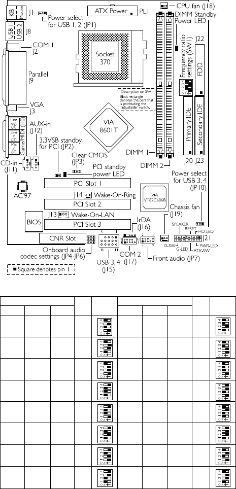
CM33-TCPower Select for USB 1, 2(JP1) or USB 3, 4 (JP10)1-2 On: VCC (default)2-3 On: 5VSBOnboard Audio CodecSettings - JP4, JP5 and JP61

Comments to this Manuals

No comments